In-Situ Consolidation Mechanics in Open-Atmosphere LFAM: The Role of Compaction Force and Thermal History
A Technical Review of Process-Structure Relationships in Compaction Roller Systems for CF/PA and CF/PEEK Thermoplastic Composites
Executive Summary
In-situ consolidation (ISC) represents a paradigm shift in thermoplastic composite manufacturing, enabling single-step production without autoclave post-processing. This review examines the critical process-structure relationships governing bond strength development in open-atmosphere large format additive manufacturing (LFAM) systems that employ compaction rollers—such as those used in laser-assisted automated fiber placement (LAFP). The analysis focuses on how roller pressure and nip-point temperature dictate interlaminar bond quality in carbon fiber reinforced polyamide (CF/PA) and polyether ether ketone (CF/PEEK) systems.
However, optimized process parameters—including compaction forces of 100–2000 N, nip-point temperatures of 350–430°C, and multi-pass strategies—can achieve ILSS values representing 75–95% of autoclave benchmarks.
1. Introduction
The consolidation of thermoplastic composites without autoclave processing has emerged as a critical enabler for cost-effective, scalable manufacturing of high-performance structures [1]. Unlike thermoset systems that rely on irreversible chemical cross-linking, thermoplastic matrices achieve interlaminar bonding through physical mechanisms—intimate contact formation and polymer chain interdiffusion (healing)—that are inherently reversible and highly sensitive to processing conditions [2].
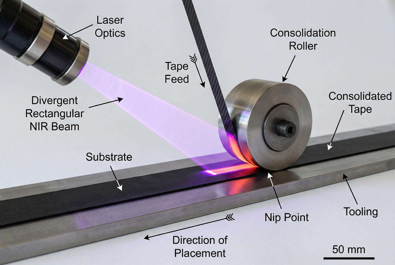
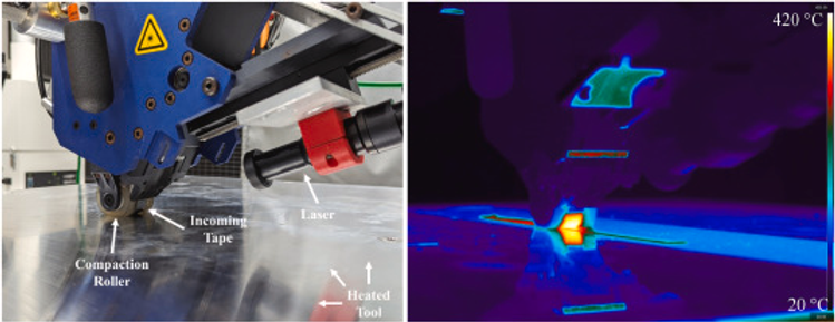
Process Schematic - Laser-Assisted AFP with Compaction Roller
Diagram illustrating the key zones in laser-assisted automated fiber placement: laser heating zone, nip point, consolidation zone under roller, and cooling region. Shows incoming tape, substrate, compaction roller, and temperature gradients.
Laser-Assisted AFP for Thermoplastic Composites
In-Situ Consolidation Process Schematic
Temperature Profile Through Process
Source: Adapted from Stokes-Griffin & Compston, "Laser-assisted AFP for thermoplastic composites," Composites Part A, 2015. DOI: 10.1016/j.compositesa.2015.04.017
In open-atmosphere LFAM, the absence of autoclave pressure (typically 0.3–0.7 MPa) and controlled cooling environments fundamentally alters the consolidation physics [3]. The compaction roller must simultaneously: (1) eliminate surface asperities to establish intimate contact, (2) maintain sufficient temperature for polymer chain mobility, (3) apply pressure to suppress void growth, and (4) accommodate geometric variations in the substrate [4].
This review synthesizes recent advances in understanding these coupled phenomena, with emphasis on quantitative models for intimate contact and healing, the role of roller design in pressure distribution, and the relationship between thermal history and final part quality.
2. Thermodynamics of Fusion Bonding
2.1 The Two-Stage Bonding Model
Interlaminar bonding in thermoplastic composites proceeds through two sequential but overlapping mechanisms: intimate contact development and polymer healing (autohesion) [5]. The total degree of bonding (Db) is expressed as the product of these contributions:
Db = Dic · Dh
where Dic is the degree of intimate contact (ratio of actual to nominal contact area) and Dh is the degree of healing (ratio of achieved to ultimate bond strength) [6].
2.2 Intimate Contact: The Lee-Springer Model
The pioneering work of Lee and Springer [7] established the quantitative framework for intimate contact development. Their model represents surface roughness as a series of identical rectangular asperities that deform under applied pressure and elevated temperature.
Intimate Contact Development Schematic
Surface Asperity Deformation During Thermoplastic Consolidation
Intimate Contact Evolution
Source: Lee & Springer, "Manufacturing process of thermoplastic matrix composites," J. Composite Materials, 1987. DOI: 10.1177/002199838702101101
The model reveals that time for full intimate contact (tic) is proportional to viscosity and inversely proportional to pressure. For PEEK at 400°C with a viscosity of approximately 500–1000 Pa·s and applied pressures of 0.1–1 MPa, the required intimate contact time ranges from 10 to 500 ms [8]. This presents a fundamental challenge for high-speed AFP, where contact times under the roller are often limited to 10–100 ms at layup velocities of 20–200 mm/s [9].
2.3 Polymer Healing: Reptation Theory
Once intimate contact is established, bond strength develops through the interdiffusion of polymer chains across the interface—a process described by de Gennes' reptation theory [10]. The degree of healing under isothermal conditions follows a characteristic relationship where the welding time (tw) is required for full strength recovery [11].
For non-isothermal processing typical of AFP, Yang and Pitchumani [12] developed an integral formulation. The welding time exhibits Arrhenius-type temperature dependence.
Reptation/Welding Times for Engineering Thermoplastics
| Material | Temperature (°C) | Welding Time tw (ms) | Activation Energy Ea (kJ/mol) |
|---|---|---|---|
| PEEK | 370 | 177 | 150–200 |
| PEEK | 400 | 95 | 150–200 |
| PEEK | 430 | 71 | 150–200 |
| PEKK | 360 | 120–180 | 140–190 |
| PA6 | 250 | 50–100 | 80–120 |
| PPS | 310 | 80–150 | 100–140 |
Data compiled from [11, 13, 14]
Critical Insight
For AS4/PEEK, full healing requires 71–177 ms at typical processing temperatures—often exceeding the contact time available under the compaction roller [9].
2.4 Crystallization Kinetics and the Processing Window
Semi-crystalline thermoplastics exhibit a narrow "processing window" bounded by the melting temperature (Tm) and degradation limits above, and crystallization/vitrification below [15]. For PEEK:
Crystallinity vs. Cooling Rate
Effect of Thermal History on Semi-Crystalline Thermoplastic Composites
Material Properties Comparison
| Property | CF/PEEK | CF/PA6 |
|---|---|---|
| Max Crystallinity (Slow Cool) | ||
| ISC Range Crystallinity | ||
| Crystallization Rate | Slower | Faster |
| Service Temperature | 250°C+ | 80-120°C |
| AFP Processability | High Tprocess | Lower Tprocess |
Source: Lee et al., "Effect of temperature history on crystalline morphology of PEEK," Composites Part A, 2022. DOI: 10.1016/j.compositesa.2022.106836
Cooling rate profoundly impacts crystallinity development [16]:
Crystallinity as a Function of Cooling Rate
| Material | Cooling Rate (°C/s) | Crystallinity (%) | Morphology |
|---|---|---|---|
| PEEK | 0.1–1 (autoclave) | 30–35 | Large spherulites (15–30 μm) |
| PEEK | 10–50 (hot press) | 25–30 | Medium spherulites |
| PEEK | 100–500 (AFP) | 17–25 | Small spherulites |
| PEEK | >1000 (rapid quench) | 9–17 | Microspherulitic/amorphous |
| PA6 | 0.5–5 | 36–50 | α-phase dominant |
| PA6 | >250 | 15–28 | Mixed α/γ, reduced crystallinity |
Data from [16, 17, 18]
In laser-assisted AFP, cooling rates can exceed 1000°C/s, leading to crystallinity levels of 9–17%—significantly below the 30–40% achieved in autoclave processing [19]. This reduced crystallinity affects:
Chemical resistance (lower)
Long-term creep resistance (lower)
Impact toughness (often higher)
Interlaminar bond strength (variable)
3. Compaction Dynamics
3.1 The Role of the Compaction Roller
The compaction roller serves multiple functions in ISC [20]:
Pressure application for intimate contact development
Heat retention at the nip point during bonding
Void suppression through consolidation pressure
Geometric conformability to curved or variable-thickness substrates
Compaction Roller Configurations—Rigid vs. Deformable
Side-by-side comparison of rigid metal roller and deformable silicone roller showing contact geometry, pressure distribution, and conformability to curved surfaces.
Compaction Roller Design Comparison
Rigid vs. Deformable Roller Contact Mechanics
Key Performance Metrics
• High-pressure consolidation needs
• Precise layup control
• Thermoplastic tape with low tack
• Variable thickness transitions
• Better void consolidation
• Thermoset prepreg applications
Source: AddComposites, "Deep Dive into Compaction Roller Design," 2023. addcomposites.com
3.2 Hertzian Contact Mechanics
For a rigid cylindrical roller pressed against a flat substrate, classical Hertzian contact theory provides the pressure distribution [21]. The contact half-width (a) and maximum pressure (pmax) depend on applied force (F), roller radius (R), roller/tape width (L), and effective modulus (E*).
For typical AFP conditions (F = 100–500 N, R = 20–40 mm, L = 6.35–25 mm), contact half-widths of 1–3 mm are achieved with peak pressures of 0.5–5 MPa [22].
3.3 Rigid vs. Deformable Rollers
Comparison of Compaction Roller Types
| Parameter | Rigid Roller | Deformable (Silicone) Roller |
|---|---|---|
| Material | Steel, aluminum, hard polymer | Silicone rubber (Shore A 25–60) |
| Contact width | 2–5 mm | 10–25 mm |
| Pressure distribution | Sharp peak (Hertzian) | Broader, more uniform |
| Conformability | Poor (gaps on curves) | Good (adapts to R > 50 mm) |
| Max temperature | >500°C (metal) | 250–300°C (silicone limit) |
| Contact time at 100 mm/s | 20–50 ms | 100–250 ms |
| Applications | Hot-gas torch AFP, high-temp | Laser AFP, moderate curves |
Compiled from [22, 23, 24]
Recent research has demonstrated that softer rollers (Shore A ~28) show a larger force control window and better suitability for curved tools, while maintaining sufficient pressure for consolidation [23]. However, silicone temperature limits (~300°C continuous) can be problematic for PEEK processing at 380–430°C, necessitating active cooling or metal-core designs.
3.4 Pressure Distribution and Process Window
Experimental studies using pressure-sensitive films and embedded sensors reveal that increasing tool curvature leads to decreased compaction pressure uniformity [23]. A novel variable-pressure roller design achieved a 24% reduction in wrinkle defects compared to conventional rollers by adapting pressure distribution to local geometry [25].
Effect of Compaction Force on Consolidation Quality
| Compaction Force (N) | Contact Time (ms) | Void Content (%) | ILSS (MPa) |
|---|---|---|---|
| 48 | 50 | 4.2 | 45.8 |
| 109 | 50 | 2.8 | 49.9 |
| 500 | 50 | 1.5 | 58.3 |
| 1000 | 50 | 0.9 | 65.2 |
| 2000 | 50 | 0.5 | 68.7 |
Data from CF/PEEK at 11 m/min layup speed [26]
The data demonstrate that void content decreases monotonically with increasing compaction force, falling below 2% when roller pressure reaches 2000 N at moderate speeds.
4. Thermal Hysteresis
4.1 Temperature Profile at the Nip Point
The nip point—defined as the first contact between incoming tape and substrate under the roller—represents the critical location where bonding initiates [27]. Temperature at this point must exceed the matrix melting temperature for sufficient time to enable intimate contact and healing.
Thermal Profile in the Consolidation Zone
Temperature vs. position plot showing the thermal history of a material element passing through the laser heating zone, nip point, and roller contact region.
Temperature Profile Along Process Position
Thermal History During Laser-Assisted AFP Consolidation
Process Zone Details
Source: Danezis et al., "In-process nip point temperature estimation," J. Composite Materials, 2023. DOI: 10.1177/08927057221122095
4.2 Laser Power and Placement Speed Interactions
The Linear Energy Density of Consolidated Segments (LEDCS) provides a useful metric for characterizing the relationship between laser power and placement speed [28]:
LEDCS = Plaser / vplacement (J/mm)
Experimental optimization has shown that ILSS values exceeding 50 MPa are achieved within LEDCS range of 1.58–3.75 J/mm for CF/PEEK [28].
Nip Point Temperature and ILSS Relationship
| Nip Point Temp (°C) | Placement Speed (mm/s) | Laser Power (W) | ILSS (MPa) |
|---|---|---|---|
| 320 | 100 | 400 | 42.3 |
| 350 | 100 | 550 | 59.9 |
| 380 | 100 | 700 | 65.4 |
| 400 | 100 | 850 | 58.1 (degradation onset) |
| 350 | 150 | 650 | 52.7 |
| 350 | 200 | 800 | 48.3 |
Data from [27, 29]
The data reveal a non-monotonic relationship: ILSS increases with nip point temperature up to approximately 380–400°C, beyond which thermal degradation reduces bond quality.
4.3 Through-Thickness Temperature Gradients
A critical challenge in AFP is the steep through-thickness temperature gradient, often exceeding 1000°C/s in cooling rate [30]. For a given nip point temperature, increasing deposition velocity escalates this gradient on the incoming tape, potentially leading to:
- Incomplete melting at the interface center
- Surface degradation while core remains below Tm
- Residual thermal stresses from differential cooling
Models incorporating Lagrangian tracking of material elements through the consolidation zone have improved prediction of actual interface temperatures, enabling better process control [31].
4.4 Heat Source Configurations
Several heating technologies are employed in open-atmosphere ISC:
Comparison of Heat Sources for ISC
| Heat Source | Max Temp (°C) | Heating Rate (°C/s) | Control | Advantages | Limitations |
|---|---|---|---|---|---|
| Diode Laser | >600 | 1000–5000 | Excellent | Precise, fast response | Absorptivity variations |
| Hot Gas Torch | ~500 | 100–500 | Moderate | Simple, uniform | Slower, convective losses |
| IR Lamp | ~450 | 200–800 | Good | Broad coverage | Lower intensity |
| Ultrasonic | N/A | Frictional | Moderate | No external heat | Complex mechanics |
Compiled from [32, 33]
Laser systems dominate high-speed PEEK processing due to their ability to rapidly achieve temperatures above 400°C with millisecond-scale control. However, carbon fiber's high absorptivity can create surface overheating while the PEEK matrix remains below melting—a key challenge addressed by optimized beam profiles and micro-surface texturing of tapes [34].
5. Defect Characterization
5.1 Void Classification in ISC
Voids in AFP-consolidated thermoplastic composites are categorized by scale and formation mechanism [35]:
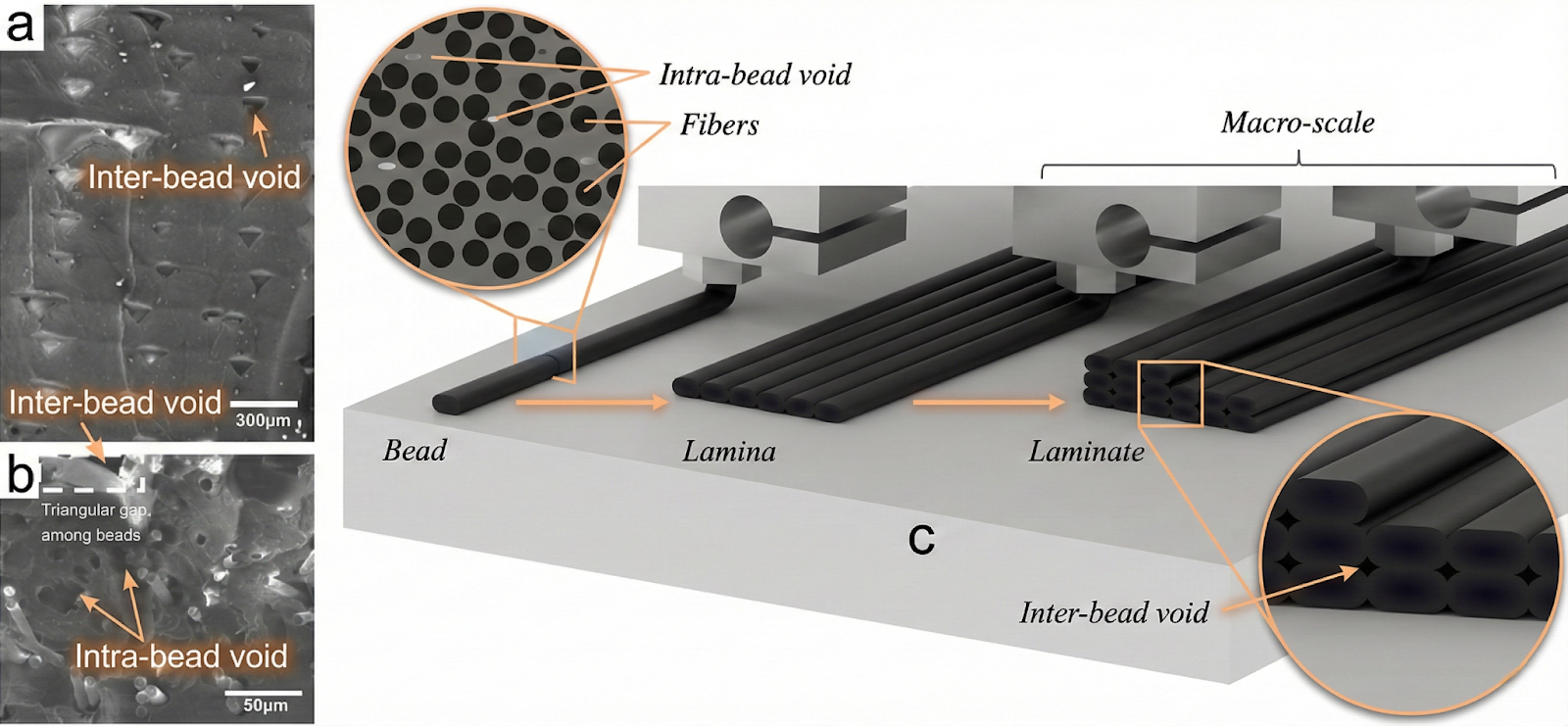
Void Types in ISC Thermoplastic Composites
Cross-sectional view showing three void types: inter-bead voids (between deposited tracks), interlaminar voids (between layers), and intra-tow voids (within fiber bundles).
Cross-Section of AFP Laminate
Void Types and Distribution in Automated Fiber Placement Structures
Void Formation Mechanisms
Impact on Mechanical Properties
Source: Mehdikhani et al., "Voids in fiber-reinforced polymer composites," J. Composite Materials, 2019. DOI: 10.1177/0021998318772152
5.2 Porosity Levels by Processing Method
Void Content Comparison Across Manufacturing Methods
| Manufacturing Method | Void Content (%) | Pressure (MPa) | Notes |
|---|---|---|---|
| Autoclave (CF/PEEK) | 0.1–0.5 | 0.3–0.7 | Gold standard |
| Hot Press | 0.3–1.0 | 0.5–2.0 | Near-autoclave quality |
| Vacuum Bag Only (VBO) | 1.0–3.0 | 0.1 | Limited by atmospheric pressure |
| AFP In-Situ (single pass) | 2.0–8.0 | 0.1–0.5 | Speed-dependent |
| AFP + Repass | 0.6–2.0 | 0.1–0.5 | Significant improvement |
| MISC (Multiple ISC) | 0.5–1.0 | 0.1–0.5 | Approaches autoclave quality |
Data from [26, 36, 37]
The data highlight that single-pass ISC typically yields 2–8% voids, while multi-pass strategies (repass, MISC) can reduce this to <1%—approaching autoclave levels.
5.3 Void Growth and Suppression Mechanisms
During ISC, void behavior is governed by competing mechanisms [38]:
Void nucleation
From dissolved gases, entrapped air, or incomplete wetting
Void growth
Driven by internal pressure exceeding matrix pressure
Void collapse
Under compaction pressure when Pcomp > Pvoid
Void stabilization
When matrix viscosity increases during cooling
For typical void sizes (10–100 μm) in PEEK, critical pressures of 0.1–1 MPa are required—explaining why AFP's limited consolidation pressure (0.05–0.3 MPa) struggles to eliminate larger voids.
5.4 Characterization Techniques
Modern void characterization employs multiple complementary techniques [35]:
- Optical microscopy: 2D sectioning, quick assessment
- Micro-CT (μCT): 3D void morphology, connectivity analysis
- Ultrasonic C-scan: Non-destructive, large-area coverage
- Density measurement: Bulk void fraction (ASTM D2734)
μCT studies of AFP CF/PA6 composites reveal average void contents of 6–7%, with interconnected inter-bead channels forming a network structure distinct from isolated intra-tow voids [39].
6. Mechanical Benchmarking
6.1 Interlaminar Shear Strength (ILSS) as Quality Metric
ILSS, measured by the short-beam shear test (ASTM D2344), provides the most direct assessment of interlaminar bond quality in thermoplastic composites [40]. It captures the combined effects of:
Intimate contact completeness
Polymer healing extent
Void content and distribution
Crystallinity at the interface
ILSS vs. Process Parameters for CF/PEEK
Interlaminar Shear Strength Comparison Across Manufacturing Methods
Key Insights
Source: Data compiled from Liu et al., J. Manufacturing Processes, 2022 and Fereidouni & Van Hoa, J. Reinforced Plastics, 2024.
6.2 ILSS Data: ISC vs. Autoclave
Comprehensive ILSS Comparison for CF/PEEK Systems
| Manufacturing Method | ILSS (MPa) | Void (%) | Crystallinity (%) | Relative Performance |
|---|---|---|---|---|
| Autoclave (reference) | 94–100 | 0.1–0.5 | 33–38 | 100% |
| Hot Press (optimal) | 70–75 | 0.5–1.0 | 28–32 | 74–79% |
| LAFP In-Situ (single) | 45–60 | 2–6 | 10–20 | 47–63% |
| LAFP In-Situ (optimized) | 60–70 | 1–3 | 18–25 | 63–74% |
| LAFP + Repass | 65–75 | 0.8–2 | 25–32 | 68–79% |
| MISC (Multi-pass ISC) | 85–90 | 0.5–1 | 35–39 | 89–95% |
| LAFP + Hot Press Temper | 73 | 0.5 | 30+ | 77% |
Data compiled from [26, 28, 37, 41, 42]
6.3 Effect of Process Parameters on ILSS
Systematic studies reveal the relative importance of process parameters [28]:
Ranking by effect size (ANOVA analysis):
- Laser Power × Placement Speed interaction (most significant)
- Tooling (substrate) temperature
- Compaction force
- Tape tension (least significant)
ILSS Response to Individual Parameters
| Parameter | Low Setting | High Setting | ILSS Change |
|---|---|---|---|
| Laser Power | 400 W | 700 W | +15–25 MPa |
| Placement Speed | 50 mm/s | 150 mm/s | -10–20 MPa |
| Tooling Temp | 100°C | 200°C | +8–15 MPa |
| Compaction Force | 200 N | 800 N | +5–12 MPa |
| Tape Tension | 10 N | 40 N | ±2–5 MPa |
Data from orthogonal experiment arrays [28]
6.4 Other Mechanical Properties
Mechanical Property Comparison—ISC vs. Autoclave
| Property | ISC (AFP) | Autoclave | Ratio | Notes |
|---|---|---|---|---|
| ILSS (MPa) | 50–70 | 90–100 | 0.55–0.70 | Sensitive to voids |
| 0° Tensile Strength (MPa) | 2100–2300 | 2200–2400 | 0.95–0.97 | Fiber-dominated |
| 0° Tensile Modulus (GPa) | 130–140 | 135–145 | 0.96–0.97 | Fiber-dominated |
| 90° Tensile Strength (MPa) | 60–75 | 80–95 | 0.75–0.79 | Matrix-sensitive |
| GIc (J/m²) | 1200–1600 | 1400–1800 | 0.86–0.89 | Mode I fracture |
| GIIc (J/m²) | 1800–2400 | 2200–2800 | 0.82–0.86 | Mode II fracture |
Compiled from [41, 43]
Fiber-dominated properties (0° tensile) show minimal degradation (<5%), while matrix- and interface-dominated properties exhibit the largest gaps—particularly ILSS (30–45% reduction).
7. Future Directions
7.1 Multi-Pass and Hybrid Strategies
The MISC (Multiple In-Situ Consolidation) approach demonstrates that autoclave-equivalent properties are achievable through optimized multi-pass strategies [37]. Key developments include:
- Laser re-heating passes: Additional thermal cycles without material deposition
- Staged consolidation: Progressive pressure application over multiple passes
- Hybrid ISC + post-consolidation: AFP followed by localized hot pressing
7.2 Advanced Process Control
Real-time control of nip-point temperature using closed-loop laser power modulation shows promise for maintaining optimal bonding conditions across varying geometries [31]. Emerging approaches include:
In-situ infrared pyrometry with <10 ms response
Model-predictive control incorporating thermal models
AI/ML optimization of parameter trajectories
7.3 Material Innovations
New material developments aim to expand the ISC processing window:
- Low-melt PAEK variants (e.g., PEKK, LM-PAEK) with reduced processing temperatures
- Surface-modified tapes with enhanced absorptivity and reduced roughness
- Interleaving films to improve interlaminar bonding
7.4 Toward Full Autoclave Equivalence
The path to true autoclave replacement requires addressing the fundamental time-temperature-pressure constraints of open-atmosphere ISC. Promising directions include:
Higher compaction pressures
(>1 MPa) through novel roller designs
Extended heating zones
For increased bonding time
Controlled cooling
To optimize crystallinity
Process integration
Combining AFP with in-line tempering
8. Conclusions
In-situ consolidation of thermoplastic composites in open-atmosphere LFAM systems remains constrained by the coupled physics of intimate contact, polymer healing, and crystallization. The key findings of this review are:
Bonding time is the critical bottleneck
At typical AFP speeds, consolidation windows of 10–100 ms are often insufficient for complete healing (requiring 70–180 ms for PEEK at optimal temperatures).
Compaction roller design significantly affects outcomes
Deformable rollers provide extended contact time and better conformability, while rigid rollers enable higher temperatures but limited contact duration.
Nip-point temperature must balance competing requirements
Temperatures of 350–400°C are optimal for CF/PEEK, with higher values risking degradation and lower values yielding incomplete bonding.
Void content is process-limited
Single-pass ISC typically achieves 2–6% voids; multi-pass strategies can reduce this to <1%.
ILSS of 70–90 MPa is achievable
Through optimized parameters and multi-pass consolidation, ISC can reach 75–95% of autoclave ILSS values.
The continued development of advanced roller designs, closed-loop process control, and hybrid consolidation strategies offers a realistic pathway to autoclave-equivalent properties without the capital and operating costs of traditional autoclave processing.
References
[1] Agarwal, K., Kuchipudi, S. K., Girard, B., & Hober, M. (2018). "Advanced thermoplastic composite manufacturing by in-situ consolidation: A review." J. Composites Science, 4(4), 149. DOI: 10.3390/jcs4040149
[2] Fereidouni, M., & Van Hoa, S. (2024). "In-situ consolidation of thermoplastic composites by automated fiber placement: Characterization of defects." J. Reinforced Plastics & Composites. DOI: 10.1177/08927057241251837
[3] Mehdikhani, M., Gorbatikh, L., Verpoest, I., & Lomov, S. V. (2019). "Voids in fiber-reinforced polymer composites: A review on their formation, characteristics, and effects on mechanical performance." J. Composite Materials, 53(12), 1579-1669. DOI: 10.1177/0021998318772152
[4] AddComposites. (2023). "Pushing the boundaries of automated fiber placement: A deep dive into compaction roller design." Available: addcomposites.com
[5] Butler, C. A., McCullough, R. L., Pitchumani, R., & Gillespie, J. W. (1998). "An analysis of mechanisms governing fusion bonding of thermoplastic composites." J. Thermoplastic Composite Materials, 11(4), 338-363. DOI: 10.1177/089270579801100404
[6] Dara, P. H., & Loos, A. C. (1985). "Thermoplastic matrix composite processing model." Virginia Polytechnic Institute Report, CCMS-85-10.
[7] Lee, W. L., & Springer, G. S. (1987). "A model of the manufacturing process of thermoplastic matrix composites." J. Composite Materials, 21(11), 1017-1055. DOI: 10.1177/002199838702101101
[8] Mantell, S. C., & Springer, G. S. (1992). "Manufacturing process models for thermoplastic composites." J. Composite Materials, 26(16), 2348-2377.
[9] AddComposites. (2023). "An in-depth look at the in-situ consolidation in thermoplastic composites." Available: addcomposites.com
[10] de Gennes, P. G. (1971). "Reptation of a polymer chain in the presence of fixed obstacles." J. Chemical Physics, 55(2), 572-579.
[11] Bastien, L. J., & Gillespie, J. W. (1991). "A non-isothermal healing model for strength and toughness of fusion bonded joints of amorphous thermoplastics." Polymer Engineering & Science, 31(24), 1720-1730. DOI: 10.1002/pen.760312406
[12] Yang, F., & Pitchumani, R. (2001). "Healing of thermoplastic polymers at an interface under nonisothermal conditions." Macromolecules, 35(8), 3213-3224. DOI: 10.1021/ma010858o
[13] Regnier, G. (2016). "Modeling of thermoplastic welding." SAM/PIMM, Arts et Métiers. Available: sam.ensam.eu
[14] JEC Composites. (2024). "Composites welding: Characterisation and prediction of adhesion kinetics." Available: jeccomposites.com
[15] Stokes-Griffin, C. M., & Compston, P. (2015). "Investigation of sub-melt temperature bonding of carbon-fibre/PEEK in an automated laser tape placement process." Composites Part A, 84, 17-25.
[16] Lee, A., Wynn, M., Quigley, L., Salviato, M., & Zobeiry, N. (2022). "Effect of temperature history during additive manufacturing on crystalline morphology of polyether ether ketone." Composites Part A, 163, 107204. DOI: 10.1016/j.compositesa.2022.107204
[17] Tanniru, M., & Mada, M. R. (2024). "Crystallinity of neat and carbon fiber-reinforced polyamide-6 processed at different cooling rates." Composites Part A, 186, 108395. DOI: 10.1016/j.compositesa.2024.108395
[18] Comelli, C. A., et al. (2024). "Observation of PEEK melting peaks within the additive manufacturing material extrusion process." Macromol. Mater. Eng., 309, 2300386.
[19] Hudson, T., et al. (2023). "Thermal response of thermoplastic composite tape during in-situ consolidation." SAMPE 2023. NASA Technical Reports: ntrs.nasa.gov
[20] Electroimpact. (2023). "In-situ consolidation AFP thermoplastics." HiCAM White Paper. Available: electroimpact.com
[21] Johnson, K. L. (1985). Contact Mechanics. Cambridge University Press.
[22] Peeters, D., et al. (2023). "Analysis of roller compaction pressure distribution in automated dry fibre placement." Composite Structures, 320, 117187. DOI: 10.1016/j.compstruct.2023.117187
[23] Rajan, S., et al. (2025). "A novel compaction roller with variable pressure distribution and contact time for automated fiber placement." Composites Part A, 188, 108521. DOI: 10.1016/j.compositesa.2024.108521
[24] Borflex Composites. (2023). "Fiberroll compacting AFP roller range." CompositesWorld. Available: compositesworld.com
[25] AddComposites. (2024). "High-temperature compaction rollers for advanced fiber placement." Available: addcomposites.com
[26] Liu, J., Wang, S., Yang, H., Zhu, D., & Guo, Y. (2024). "Processing and characterization of high-performance thermoplastic composites manufactured by laser-assisted automated fiber placement in-situ consolidation and hot-press." J. Industrial Textiles, 54. DOI: 10.1177/15589250241254440
[27] Danezis, A., Williams, D., & Skordos, A. A. (2023). "In-process nip point temperature estimation in automated tape placement based on analytical solution and remote thermal measurements." J. Composite Materials, 57(3), 493-506. DOI: 10.1177/08927057221122095
[28] Guo, J., et al. (2024). "Influence of process parameters on the interlaminar shear strength of CF/PEEK composites in-situ consolidated by laser-assisted automated fiber placement." Composites Part B, 284, 111679. DOI: 10.1016/j.compositesb.2024.111679
[29] Li, Z., et al. (2025). "Multi-objective optimization of laser heat flux distribution considering interlaminar shear strength and warping in laser-assisted automated fiber placement." Polymer Composites. DOI: 10.1002/pc.29964
[30] CompositesWorld. (2023). "Consolidating thermoplastic composite aerostructures in place, Part 2." Available: compositesworld.com
[31] Santos, R. A., et al. (2025). "A transient thermal model within the laser shadow during laser-assisted automated fiber placement." Composites Part B, 290, 112029. DOI: 10.1016/j.compositesb.2025.112029
[32] Stokes-Griffin, C. M., & Compston, P. (2015). "Optical characterisation and modelling for oblique near-infrared laser heating of carbon fibre reinforced thermoplastic composites." Optics and Lasers in Engineering, 72, 1-11.
[33] Khan, M. A., et al. (2022). "Review: Filament winding and automated fiber placement with in situ consolidation for fiber reinforced thermoplastic polymer composites." Polymers, 13(12), 1951. DOI: 10.3390/polym13121951
[34] Sun, Y., et al. (2024). "Optical properties optimization of carbon fiber reinforced thermoplastic tapes by micro surface texturing for enhanced laser heating efficiency." Composites Part A, 180, 108090. DOI: 10.1016/j.compositesa.2024.108090
[35] Mehdikhani, M., et al. (2019). "Voids in fiber-reinforced polymer composites: A review." J. Composite Materials, 53(12), 1579-1669. DOI: 10.1177/0021998318772152
[36] Hu, W., Centea, T., & Nutt, S. (2020). "Effects of material and process parameters on void evolution in unidirectional prepreg during vacuum bag-only cure." J. Composite Materials, 54(10), 1279-1290. DOI: 10.1177/0021998319864420
[37] Zhang, D., et al. (2023). "Effect of voids and crystallinity on the interlaminar shear strength of in-situ manufactured CF/PEEK laminates using repass treatment." Composites Part A, 166, 107391.
[38] PMC. (2022). "Research on void dynamics during in situ consolidation of CF/high-performance thermoplastic composite." Polymers, 14(6), 1247. DOI: 10.3390/polym14061247
[39] Sommacal, S., et al. (2021). "Fibre flow and void formation in 3D printing of short-fibre reinforced thermoplastic composites." Additive Manufacturing, 46, 102187. DOI: 10.1016/j.addma.2021.102187
[40] ZwickRoell. (2023). "Interlaminar shear strength (ILSS) ASTM D2344." Available: zwickroell.com
[41] Shi, Y., et al. (2023). "Interlaminar shear strength of Carbon/PEEK thermoplastic composite laminate: Effects of in-situ consolidation by automated fiber placement and autoclave re-consolidation." Composites Part B, 269, 111105. DOI: 10.1016/j.compositesb.2023.111105
[42] Chen, J., et al. (2021). "Effect of consolidation force on interlaminar shear strength of CF/PEEK laminates manufactured by laser-assisted forming." Composite Structures, 266, 113779. DOI: 10.1016/j.compstruct.2021.113779
[43] Shin, K., et al. (2023). "CF/PEEK interleaved laminates with PEEK film interleaving manufactured by laser-assisted forming: Microstructure and interlaminar shear strength." Composites Part A, 169, 107527. DOI: 10.1016/j.compositesa.2023.107527
Learn More
Have questions about implementing in-situ consolidation for your thermoplastic composite manufacturing?
Contact Us for a Consultation